
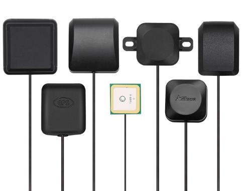
Active GNSS antennas for positioning, timing and high-precision survey applications. This page covers how the class behaves specifically in antenna polarization explained work, and lists the 2 catalog models that fit.
What this class does well
An active GNSS antenna with an integrated LNA sets the noise figure of the whole receive chain at the antenna, before the cable loss, which is what allows a usable signal after a long coaxial run to the receiver.
Where it falls down
It needs a DC bias up the coaxial line, so the receiver has to supply it, and the LNA that gives the sensitivity also means a nearby transmitter can saturate the front end.
The range we stock
Across the 2 models in this class the gain runs from 28 to 35 dBi, frequency coverage from 1176 to 1606 MHz, and the longest dimension from 50 mm to 152 mm. Check the size figure early. It decides the mount, and on a shared mast it decides whether the part fits at all.
GNSS / GPS Antenna models
| Model | Band (MHz) | Gain | Polarization | Length | Connector |
|---|---|---|---|---|---|
| AW-GP1575-28 | 1575–1606 | 28 dBi | RHCP | 50 mm | SMA-Male |
| AW-GP1227-35 | 1176–1606 | 35 dBi | RHCP | 152 mm | TNC-Female |
Specifying one for antenna polarization explained
Vertical polarization is standard for omnidirectional mobile and broadcast use; horizontal and circular polarizations are chosen to reduce interference or to handle reflective and orientation-varying paths. Confirm the connector before ordering: changing the interface later means either an adapter, which adds a mismatch and a failure point, or a re-terminated cable. Standard builds ship with an SMA-Male interface.