
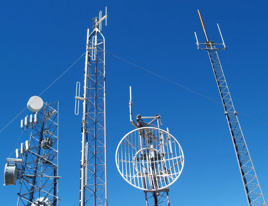
Choosing antenna polarization explained is a sequence of constraints, not a search for the highest number on the datasheet. Band comes first, then pattern, then the mount, then the connector and cable. Work them in that order and the shortlist usually comes down to two or three models.
Step 1 — Fix the band
Everything else is downstream of this. An antenna that is 200 MHz off band will still show a plausible VSWR on a cheap meter and still pass traffic on a short link, which is exactly why band errors survive to the field. Take the band from the radio datasheet, not from the marketing name of the standard.
Step 2 — Choose the pattern before the gain
Gain is not a free parameter. An omnidirectional antenna buys gain by squashing the elevation pattern, so a 12 dBi collinear on a tall mast can shoot straight over a subscriber at the base of it. A directional antenna buys gain by narrowing azimuth, which is fine on a fixed link and a problem on anything that moves or gets re-aimed by wind. Decide the shape of the coverage you need, then take the highest gain that still fits that shape.
Step 3 — Check the mount and the wind
Vertical polarization is standard for omnidirectional mobile and broadcast use; horizontal and circular polarizations are chosen to reduce interference or to handle reflective and orientation-varying paths. A longer aperture is a larger sail. If the mast or the bracket was sized for the antenna it currently carries, a higher-gain replacement is a structural change, not a like-for-like swap.
Step 4 — Connector, cable and loss
Most models here terminate in an N-Female interface. Budget the feedline loss before comparing gain figures between models: at 2.4 GHz a 10 m run of RG58 costs roughly 6 dB, which erases the difference between a 9 dBi and a 15 dBi antenna. Either shorten the run, move to a lower-loss cable, or mount the radio at the antenna.
Step 5 — Confirm the environmental rating
An IP65 housing survives jetted water; IP67 survives temporary immersion. For coastal, marine or chemical sites the radome material and the connector plating matter more than the IP number, because the failure mode there is corrosion at the interface rather than water in the body.
Shortlist
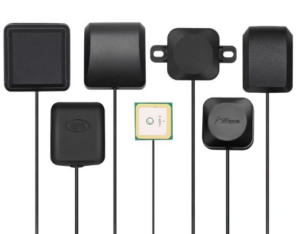
AW-GP1575-28
- Band: 1.6-1.6 GHz
- Gain: 28 dBi
- Connector: SMA-Male
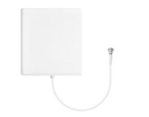
AW-PA5158-V18B65
- Band: 5.1-5.9 GHz
- Gain: 18 dBi
- Connector: N-Female

AW-PA7090-V18B65
- Band: 698-960 MHz
- Gain: 18 dBi
- Connector: N-Female
AW-PA8090-V18B65
- Band: 806-960 MHz
- Gain: 18 dBi
- Connector: N-Female
AW-PA5158-V15B65
- Band: 5.1-5.9 GHz
- Gain: 15 dBi
- Connector: N-Female
AW-PA7090-V15B65
- Band: 698-960 MHz
- Gain: 15 dBi
- Connector: N-Female