
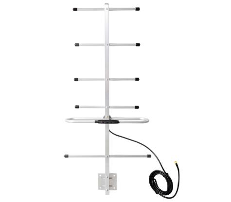
The 700-900 MHz (4G Low Band) segment spans 698 to 960 MHz and is used for lte band 12/13/5, cellular. Wavelength at the center of this band is roughly 362 mm, which sets the physical size of every resonant element and, with it, the gain a given form factor can reach.
Why the band sets the antenna size
A half-wave dipole at the center of the 700-900 MHz (4G Low Band) band is about 181 mm long, and a quarter-wave element about half that. Every practical antenna in this band is a variation on that dimension: a collinear omni stacks several half-wave sections to trade elevation beamwidth for gain, a panel places elements over a reflector, and a Yagi adds parasitic directors ahead of the driven element. There is no way to get more gain out of the same aperture, so a higher gain figure on this band always means a physically larger part.
This range is the practical sweet spot for wide-area coverage: enough diffraction and building penetration to serve a cell of several kilometers, with antennas that are still small enough to mount on ordinary hardware.
Band summary
| Frequency range | 698–960 MHz |
|---|---|
| Center wavelength | 362 mm |
| Half-wave element | 181 mm |
| Typical service | LTE Band 12/13/5, cellular |
| Catalog models | 144 |
Gain options on 700-900 MHz (4G Low Band)
| Gain | Shortest model at that gain | Length | Elevation beamwidth |
|---|---|---|---|
| 2 dBi | AW-SPR0827-2 | 26 mm | 75° |
| 3 dBi | AW-FPC0827-3 | 55 mm | 90° |
| 4 dBi | AW-CMB-5-5GGPSWIFI | 150 mm | 55° |
| 5 dBi | AW-ID0827-5 | 185 mm | 30° |
| 6 dBi | AW-TV-IN-6 | 320 mm | 70° |
| 8 dBi | AW-FGS0827-8 | 1100 mm | 20° |
| 9 dBi | AW-WM0912-9 | 210 mm | 40° |
| 10 dBi | AW-PA7090-V10B120 | 720 mm | 30° |
| 11 dBi | AW-ID0827-11 | 295 mm | 55° |
| 12 dBi | AW-YG0890-12 | 465 mm | 40° |
| 13 dBi | AW-LP4386-13 | 1450 mm | 40° |
| 15 dBi | AW-PA8090-V15B65 | 1300 mm | 15° |
| 17 dBi | AW-TV-UHF-17 | 1250 mm | 28° |
| 18 dBi | AW-YG0890-18 | 1290 mm | 25° |
Stacking Yagi Antennas models in this band
| Model | Band (MHz) | Gain | Polarization | Length | Connector |
|---|---|---|---|---|---|
| AW-YG0890-18 | 824–960 | 18 dBi | Vertical | 1290 mm | N-Female |
| AW-YG0890-12 | 824–960 | 12 dBi | Vertical | 465 mm | N-Female |
| AW-PA7090-V18B65 | 698–960 | 18 dBi | Vertical | 2570 mm | N-Female |
| AW-PA7090-V15B65 | 698–960 | 15 dBi | Vertical | 1360 mm | N-Female |
| AW-LP4386-13 | 430–860 | 13 dBi | Vertical | 1450 mm | N-Female |
| AW-FG0890-12 | 824–890 | 12 dBi | Vertical | 1550 mm | N-Female |
| AW-PA7090-V12B65 | 698–960 | 12 dBi | Vertical | 720 mm | N-Female |
| AW-PA7090-V11B90 | 698–960 | 11 dBi | Vertical | 720 mm | N-Female |
| AW-PA7090-V10B120 | 698–960 | 10 dBi | Vertical | 720 mm | N-Female |
| AW-WM0912-9 | 902–928 | 9 dBi | Vertical | 210 mm | N-Female |
| AW-GUN0827-5 | 698–2700 | 5 dBi | Vertical | 230 mm | N-Female |
| AW-PA7090-X2x15B65 | 698–960 | 2x15 dBi | Dual ±45° slant | 1360 mm | N-Female |
Matching the band to the link
Free-space loss at the center of this band is about 91 dB over one kilometer. Add the loss of the feedline, subtract the gain at both ends, and compare the result against the receiver sensitivity for the modulation you intend to run. If the margin is under roughly 10 dB the link will work on a clear day and drop in rain or foliage, which is usually the point at which a higher-gain aperture or a shorter cell radius becomes the cheaper fix.