
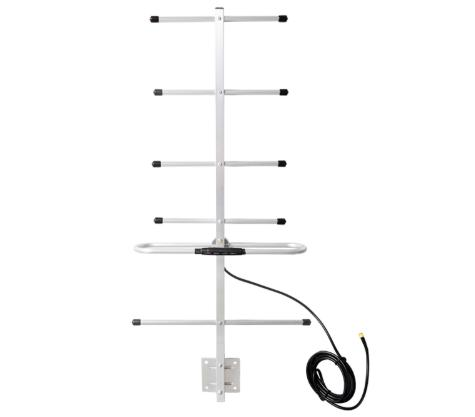
STL / Studio-Transmitter Link places its own demands on the antenna: the link budget, the interference environment and the physical install all differ from a generic stacking yagi antennas deployment. This page works through those requirements and maps them onto specific models.
What the application demands
This deployment sets its own constraints on the antenna: the link budget, the interference environment, the physical mounting and the environmental exposure all have to be specified together rather than one at a time.
Turning that into a specification
- Take the operating band from the radio datasheet, including any guard at the band edges.
- Decide the coverage shape first, omnidirectional or sector, and only then take the highest gain that still fits it.
- Measure the feedline run and subtract its loss before comparing antenna gain figures.
- Confirm the connector on the radio and order the matching interface rather than adapting in the field.
Models used for STL / Studio-Transmitter Link
| Model | Band (MHz) | Gain | Polarization | Length | Connector |
|---|---|---|---|---|---|
| AW-YG0890-18 | 824–960 | 18 dBi | Vertical | 1290 mm | N-Female |
| AW-YG0450-12 | 450–470 | 12 dBi | Vertical | 870 mm | N-Female |
| AW-YG0890-12 | 824–960 | 12 dBi | Vertical | 465 mm | N-Female |
| AW-YG2400-18 | 2400–2483 | 18 dBi | Vertical | 580 mm | N-Female |
| AW-YG1922-16 | 1720–2170 | 16 dBi | Vertical | 610 mm | N-Female |
| AW-YG0433-12 | 428–438 | 12 dBi | Vertical | 920 mm | N-Female |
Grounding and surge protection
A stacked array presents more metal at height; bond the support structure and install a surge arrestor on the combined feed.