
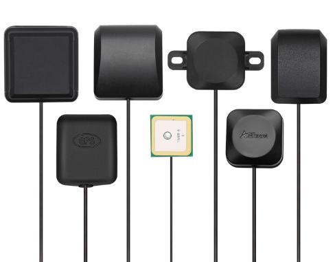
The GNSS / GPS segment spans 1176 to 1606 MHz and is used for gps l1/l2/l5, glonass, galileo, beidou. Wavelength at the center of this band is roughly 216 mm, which sets the physical size of every resonant element and, with it, the gain a given form factor can reach.
Why the band sets the antenna size
A half-wave dipole at the center of the GNSS / GPS band is about 108 mm long, and a quarter-wave element about half that. Every practical antenna in this band is a variation on that dimension: a collinear omni stacks several half-wave sections to trade elevation beamwidth for gain, a panel places elements over a reflector, and a Yagi adds parasitic directors ahead of the driven element. There is no way to get more gain out of the same aperture, so a higher gain figure on this band always means a physically larger part.
Above 1 GHz propagation becomes noticeably more line-of-sight dependent. Coverage holds well outdoors with clear sight lines, but each interior wall costs several dB and foliage in the path is a seasonal variable rather than a fixed loss.
Band summary
| Frequency range | 1176–1606 MHz |
|---|---|
| Center wavelength | 216 mm |
| Half-wave element | 108 mm |
| Typical service | GPS L1/L2/L5, GLONASS, Galileo, BeiDou |
| Catalog models | 128 |
Gain options on GNSS / GPS
| Gain | Shortest model at that gain | Length | Elevation beamwidth |
|---|---|---|---|
| 2 dBi | AW-CP-BD-MINI-1212 | 12 mm | 100° |
| 3 dBi | AW-CP-GPS-1818 | 18 mm | 95° |
| 4 dBi | AW-CP-GPS-2525 | 25 mm | 90° |
| 5 dBi | AW-ID0827-5 | 185 mm | 30° |
| 6 dBi | AW-SCF0827-6 | 420 mm | 32° |
| 9 dBi | AW-ID0827-9 | 295 mm | 60° |
| 11 dBi | AW-ID0827-11 | 295 mm | 55° |
| 12 dBi | AW-PA8025-H12B65 | 660 mm | 30° |
| 28 dBi | AW-CP-BD-2535 | 25 mm | 90° |
| 35 dBi | AW-GP1227-35 | 152 mm | 90° |
Marine and Vessel Antennas models in this band
| Model | Band (MHz) | Gain | Polarization | Length | Connector |
|---|---|---|---|---|---|
| AW-GP1575-28 | 1575–1606 | 28 dBi | RHCP | 50 mm | SMA-Male |
| AW-FGL0827-6 | 698–2700 | 6 dBi | Vertical | 620 mm | SMA-Male |
| AW-MG1880-3 | 890–1880 | 3 dBi | Vertical | 160 mm | SMA-Male |
| AW-GP1227-35 | 1176–1606 | 35 dBi | RHCP | 152 mm | TNC-Female |
| AW-CP-BD-2535 | 1561–1606 | 28 dBi | RHCP | 25 mm | IPEX MHF (U.FL) |
| AW-CP-GPS-2525A | 1575–1576 | 28 dBi | RHCP | 25 mm | IPEX MHF (U.FL) |
| AW-LP0838-12 | 800–3800 | 12 dBi | Vertical | 760 mm | N-Female |
| AW-PA8025-H12B65 | 806–2500 | 12 dBi | Horizontal | 660 mm | N-Female |
| AW-PA8025-V12B65 | 806–2500 | 12 dBi | Vertical | 660 mm | N-Female |
| AW-LP0827-11 | 698–2700 | 11 dBi | Vertical | 640 mm | N-Female |
| AW-SCH0827-9 | 698–2700 | 9 dBi | Vertical | 780 mm | N-Male |
| AW-SCF0827-6 | 698–2700 | 6 dBi | Vertical | 420 mm | SMA-Male |
Matching the band to the link
Free-space loss at the center of this band is about 95 dB over one kilometer. Add the loss of the feedline, subtract the gain at both ends, and compare the result against the receiver sensitivity for the modulation you intend to run. If the margin is under roughly 10 dB the link will work on a clear day and drop in rain or foliage, which is usually the point at which a higher-gain aperture or a shorter cell radius becomes the cheaper fix.