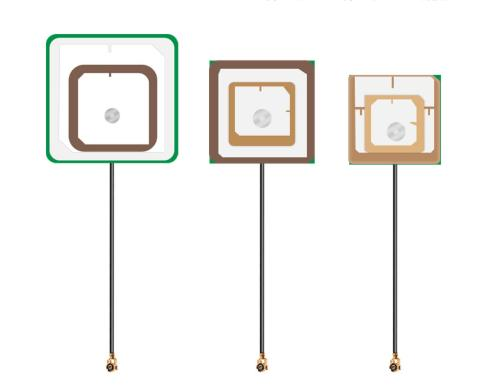
AW-CP-GPS-1818 is a 3 dBi ceramic patch antenna covering 1.6-1.6 GHz. With rhcp polarization and a rugged build, it suits gnss positioning installations in both temperate and harsh outdoor environments.
Radiation Pattern and Gain
As an omnidirectional radiator, it provides a full 360 degree azimuth pattern with an approximate 95 degree elevation beamwidth, distributing energy evenly around the mast. The rated gain of 3 dBi is referenced to an isotropic radiator.
Mechanical and Electrical Specifications
Mechanically, the AW-CP-GPS-1818 measures 18 x 18 x 4 mm and is housed in a Ceramic dielectric / silver-plated patch. The standard interface is a Solder pad connector, with a nominal impedance of 50 ohms and a typical VSWR of 2.0:1 or better. The element withstands up to 1 W of input power.
Installation Guidance
The recommended installation is embedded / internal. For best results, mount the antenna with clear line of sight to the served area and bond all outdoor hardware to a proper grounding system.
Typical Applications
GNSS Positioning
Asset Tracking
Embedded Module
Request a Quote
Need this antenna with a custom connector, cable length, or radome color? Use the antenna configurator to confirm the specification and submit an inquiry for AW-CP-GPS-1818.
Advanced filters (dimension limits)
Frequently Asked Questions
What is a ceramic patch antenna used for?
High-dielectric ceramic patch elements for GNSS and short-range links, reflow-mountable or supplied with an LNA and coaxial pigtail.
Is AW-CP-GPS-1818 suitable for gnss positioning?
Yes. AW-CP-GPS-1818 is well matched to gnss positioning deployments, where its radiation pattern and gain provide reliable coverage and link margin.
Can the connector on AW-CP-GPS-1818 be changed?
Yes. The default RF interface can be supplied as SMA, N-type, TNC, or other connectors on request, and custom cable assemblies are available. Specify your interface in the inquiry form.
What is the standard impedance and VSWR of AW-CP-GPS-1818?
The nominal impedance is 50 ohms with a typical VSWR of 1.5:1 or better across the operating band. A 75 ohm option can be quoted for broadcast applications.
How do I request a quote for AW-CP-GPS-1818?
Use the antenna configurator on this page to confirm the specification, then submit the inquiry form. An engineer from astronwireless.com will respond within one business day.
Accessories & Components
Complete your installation with matched RF cables, connectors, mounts, adapters and bulk coaxial cable. Custom assemblies, lengths and interfaces are available on request.
This website uses only necessary and functional cookies to operate, secure, and improve basic website performance.
We do not use advertising cookies, Google Analytics, or cross-site tracking technologies.
Privacy Policy