
Key Takeaways
- Real-world antenna performance often hinges on PCB layout and enclosure design, not just antenna specifications.
- Chip ceramic antennas offer a balance of size and performance for IoT devices but still require careful keep-out zone and matching.
- External antennas provide the best range and isolation at the cost of larger size and connector expense.
- Prototyping and tuning with a network analyzer is the only way to verify that a 2.4GHz antenna system is optimized.
- The antenna selection process must consider the entire RF chain, from transceiver to free space, to avoid efficiency losses.
The antenna is the final link in your IoT device’s wireless chain, directly influencing range, throughput, and battery life. Choosing the wrong 2.4GHz antenna can undermine even the best-designed radio module. This guide walks you through the essential criteria—from frequency band characteristics to antenna types and matching requirements—so you can make an informed selection that balances performance, size, and cost.
What Makes the 2.4GHz Band Ideal for IoT?
The 2.4 GHz ISM band is the workhorse of short-range wireless connectivity, hosting Wi-Fi, Bluetooth Low Energy, Zigbee, and Thread protocols. Its global regulatory acceptance allows a single hardware design to ship worldwide, simplifying logistics for B2B IoT deployments. However, the band’s popularity also means it’s crowded, with interference from Wi‑Fi routers, Bluetooth devices, and microwaves. When designing a 2.4GHz antenna for IoT, you must account for multipath reflections and co-channel interference. Antennas with good axial ratio or circular polarization can mitigate some of these issues in challenging environments, but they add complexity. The key is to select an antenna that provides sufficient link budget without excessive power consumption, a critical factor for battery-powered sensors.
Critical Performance Parameters of IoT Antennas
Effective 2.4GHz wireless antenna selection hinges on understanding a handful of technical specifications. Gain, measured in dBi, indicates how well an antenna focuses energy in a particular direction, but it doesn’t tell the whole story. A high-gain antenna may improve range in one orientation while creating dead zones in others. For most IoT applications, an omnidirectional radiation pattern is preferred, as the device’s orientation relative to the gateway is rarely fixed. Efficiency—the ratio of radiated power to input power—is equally important, especially in compact devices where the antenna’s performance can be heavily compromised by nearby components. Impedance matching (typically 50 Ω) ensures maximum power transfer, and even small mismatches from a detuned antenna can slash range by half. One often-overlooked factor is the matching network design; a well-designed Pi- or L-network can compensate for suboptimal antenna placement, but it’s not a cure‑all. Always validate antenna performance inside the final enclosure, as plastic housings and proximity to metal can shift resonance.
Comparing Antenna Types: PCB, Ceramic, and External Options
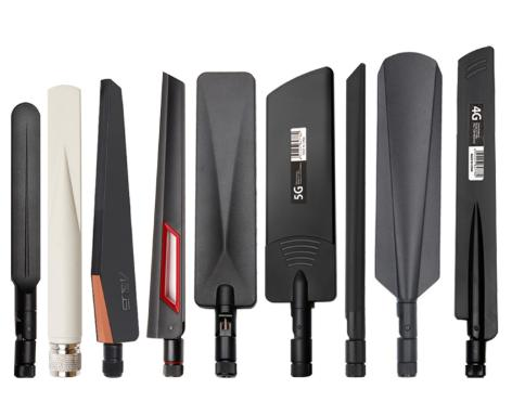
The physical form factor of your antenna dictates integration effort, cost, and performance. PCB trace antennas are the most cost-effective for high-volume IoT products, requiring only copper on the board. However, they are highly susceptible to detuning from nearby components and demand careful layout. Chip (ceramic) antennas offer a smaller footprint and better isolation from ground planes, but they still need a keep-out area and a matching network. For applications demanding maximum range, external antennas—such as whip or paddle types—are hard to beat, as they can be positioned away from noisy electronics and provide higher gain. The trade-off is increased size and external connector costs. When selecting a 2.4GHz antenna for IoT, consider your device’s size constraints, target range, and the mechanical stresses it will endure. For example, a surface‑mount ceramic antenna might be ideal for a smart sensor inside a plastic enclosure, while a ruggedized external antenna suits an outdoor gateway.
Optimizing Antenna Performance in Real-World IoT Deployments
Selecting a 2.4GHz antenna for IoT devices involves more than picking a type. The physical environment and PCB layout often have a greater impact on real-world range than the antenna’s datasheet specifications. Even a well-matched chip antenna can suffer severe detuning if placed incorrectly. When integrating a 2.4GHz antenna for IoT products, engineers must consider the entire RF signal path, from the transceiver output to the radiated wave.
Start by reviewing the ground plane and keep-out area requirements. Most small antennas—whether PCB trace, chip, or FPC—require a specific clearance zone free of copper on all PCB layers. Violating this zone shifts the resonant frequency and degrades return loss. For a chip antenna, a typical keep-out area might extend 5–10 mm in all directions, but exact dimensions depend on the vendor’s reference design. Additionally, the orientation of the antenna relative to the board edge and nearby metallic components like battery holders or connectors can dramatically alter the radiation pattern. A common pitfall is placing the antenna too close to a large ground fill, which can reflect energy back into the circuit and reduce efficiency.
The device enclosure also plays a critical role. Plastic housings are generally benign at 2.4GHz, but metalized coatings, conductive paints, and even some high-carbon plastics can attenuate signals by several dB. If a metal enclosure is unavoidable, a slot or window must be designed to allow radiation, or an external antenna used. Even the proximity of the human body can detune a wearable device’s antenna, so consider integrating a matching network that can be tuned for such body-worn scenarios. This is particularly important when the 2.4GHz wireless antenna selection involves a device that will be held or worn.
Finally, the transmission line between the RF chip and the antenna must be a controlled impedance trace (typically 50 ohms) with minimal length. Any connectors, such as U.FL or MMCX, introduce loss and potential points of failure. A quick VSWR measurement during prototyping can verify that the antenna system is correctly tuned before committing to production.
Practical Example: Tuning a Chip Antenna in a Compact Sensor
Consider a smart home sensor using a 2.4GHz chip antenna. The device is housed in a small plastic cube with a single PCB. After initial testing, the range is poor. A debug check reveals that the antenna’s keep-out zone was encroached by a copper pour for a battery pad, shifting the resonant frequency by 40 MHz. By clearing the pour and adding a simple LC matching network, the VSWR improves from 3:1 to less than 1.5:1, effectively doubling the link budget. Such real-world tuning is essential for high-volume IoT products, and antenna vendors often provide matching service or pre-tuned solutions.
| Antenna Type | Typical Gain | Form Factor | Pros | Cons | Best Use Case |
|---|---|---|---|---|---|
| PCB Trace | 1–3 dBi | Integrated on board; zero BOM cost | Very low cost, no additional part | Susceptible to detuning; requires large keep-out area and precise layout | Cost-sensitive, high-volume devices with stable enclosures |
| Chip Ceramic | 1–3 dBi | Small surface-mount component (3–8 mm) | Compact, better isolation from ground plane than PCB trace | Still needs keep-out zone and matching network; slightly higher cost | Space-constrained sensors and wearables in plastic housings |
| External Whip / Paddle | 2–5 dBi | Connectorized antenna mounted outside the device | Higher gain, easily positioned away from noise, more robust to environment | Increased size, external connector cost, and mechanical vulnerability | Gateways, outdoor nodes, and devices where range is paramount |
Next Steps for Your IoT Antenna Selection
Choosing the right 2.4GHz antenna for an IoT design is never a one-size-fits-all decision. The process begins with matching the antenna type to your product’s size, cost, and range targets, but it must continue through careful integration and testing. Start with a prototype that replicates the final mechanical assembly, then measure impedance and over-the-air performance in the target environment. If resources allow, use a network analyzer to fine-tune the matching network for peak efficiency at 2.45 GHz.
For many teams, partnering with an experienced antenna designer or leveraging vendor-provided reference designs can significantly reduce iteration cycles. As a final checklist, confirm that your selection meets these practical criteria: adequate clearance around the antenna, a 50-ohm controlled transmission line, minimal cable losses, and environmental testing for temperature and humidity extremes. When all these factors align, the antenna fades into the background and your IoT device delivers the reliable connectivity users expect.
Frequently Asked Questions
How does a PCB trace antenna compare to a chip antenna for 2.4GHz IoT devices?
PCB trace antennas are essentially free since they are printed directly on the board, making them ideal for cost-sensitive, high-volume IoT products. However, they are highly sensitive to detuning from nearby components and require a precise layout. Chip ceramic antennas are a compact alternative that offers better isolation from ground planes but still need a keep-out area and a matching network. The trade-off typically comes down to available board space and tolerance for manual tuning during development.
What is the typical range of a 2.4GHz antenna in an IoT device?
Range depends on output power, receiver sensitivity, antenna gain, and environmental factors. With a typical chip or PCB antenna (gain around 2 dBi) and standard BLE or Wi-Fi output power, line-of-sight ranges of 30 to 100 meters are common indoors. External antennas with higher gain can extend this to several hundred meters, but walls, metal objects, and interference can drastically reduce usable range. Range predictions should always be validated with field testing in the target deployment scenario.
Can I reuse a 5GHz antenna design for a 2.4GHz IoT product?
No, antennas are tuned to a specific frequency band. A 5GHz antenna is physically shorter and will not resonate efficiently at 2.4GHz, resulting in poor return loss and very low radiated power. While some dual-band antennas cover both 2.4GHz and 5GHz, they are a compromise design and may not perform as well as a dedicated single-band antenna. For an IoT device that uses only 2.4GHz, a tuned single-band antenna is the better choice.
Why does the keep-out area matter so much for a 2.4GHz chip antenna?
The keep-out area is a region on the PCB directly around the antenna that must be free of copper on all layers. This clearance is necessary for the antenna's electromagnetic fields to form correctly; any nearby metal or ground plane can capacitively load the antenna, shifting its resonant frequency away from 2.4GHz. Violating the keep-out zone can reduce antenna efficiency by 50% or more, severely limiting range. Following the manufacturer's layout recommendations for clearance is essential.
What is the best antenna type for an outdoor IoT gateway?
For an outdoor IoT gateway that requires maximum range, an external fiberglass omnidirectional or directional panel antenna is typically best. These antennas can be mounted high and away from metal structures, and they offer higher gain (5–15 dBi) than embedded antennas. This combination of elevation and gain significantly extends coverage. A wall-mount patch antenna with moderate gain is also a popular choice for wall-mounted gateways needing a directional pattern.