
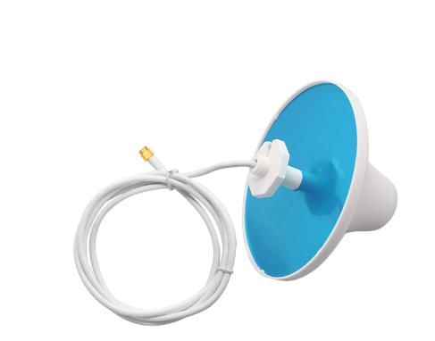
In-Building Coverage places its own demands on the antenna: the link budget, the interference environment and the physical install all differ from a generic public safety and land mobile radio antennas deployment. This page works through those requirements and maps them onto specific models.
What the application demands
Building interiors punish every dB. Concrete, low-emissivity glass and metal stud walls each take a substantial bite, so the antenna needs to be inside the space it serves rather than shooting at it through a wall.
Turning that into a specification
- Take the operating band from the radio datasheet, including any guard at the band edges.
- Decide the coverage shape first, omnidirectional or sector, and only then take the highest gain that still fits it.
- Measure the feedline run and subtract its loss before comparing antenna gain figures.
- Confirm the connector on the radio and order the matching interface rather than adapting in the field.
Models used for In-Building Coverage
| Model | Band (MHz) | Gain | Polarization | Length | Connector |
|---|---|---|---|---|---|
| AW-ID0827-11 | 698–2700 | 11 dBi | Vertical | 295 mm | N-Female |
| AW-ID0827-9 | 698–2700 | 9 dBi | Vertical | 295 mm | N-Female |
| AW-ID0827-5 | 806–2700 | 5 dBi | Vertical | 185 mm | N-Female |
| AW-ID0827-3 | 806–2700 | 3 dBi | Vertical | 185 mm | N-Female |
| AW-CBK0827-4 | 698–2700 | 4 dBi | Vertical | 190 mm | N-Male |
| AW-DT0827-3 | 698–2700 | 3 dBi | Vertical | 230 mm | SMA-Male |
| AW-CBK3538-5 | 3300–3800 | 5 dBi | Vertical | 160 mm | N-Male |
Grounding and surge protection
Tower antennas demand a full lightning-protection and grounding system per the site standard, with surge arrestors on every feed line.