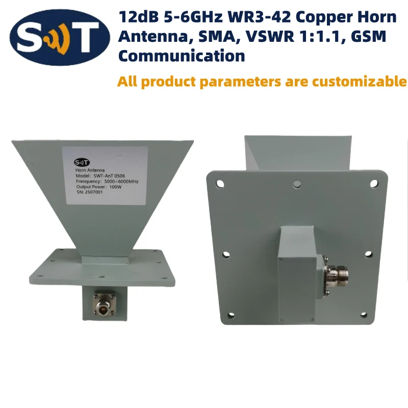
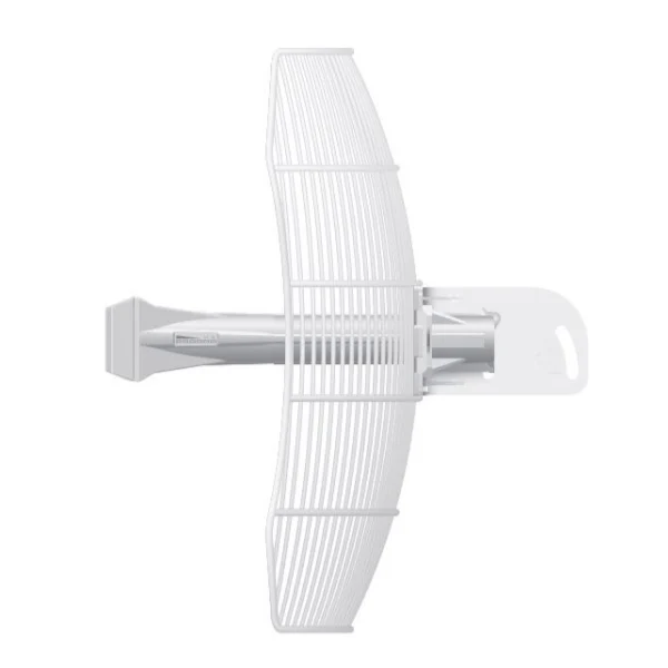
| Model | LPDP-100-500 |
|---|
| Frequency (manufacturer model field) | 100-500MHz |
|---|
| Bandwidth (manufacturer model field) | 100-500MHz |
|---|
| Gain (manufacturer model field) | 9 dBi. |
|---|
| Frequency Range | 100 - 500 MHz. |
|---|
| Gain | 9 dBi. |
|---|
| Bandwidth | Entire Band |
|---|
| Polarization | Dual (Vertical & Horizontal) |
|---|
| Input Impedance | 50 Ohms |
|---|
| Radiation Pattern | Directional |
|---|
| Beamwidth -3dB. | 65 Degrees (Horizontal) |
|---|
| Front to Back Ratio | 16 dB. |
|---|
| VSWR - Equal To or Better Then | 1:2.5 |
|---|
| RF Power Handling Capacity | 250 Watts |
|---|
| Input Termination | 2 x N-Female |
|---|
| Lightning Protection | DC Ground |
|---|
| Antenna Materials | All Aluminum |
|---|
| Mounting Hardware -Materials | Stainless Steel |
|---|
| Wind Rating | 190 Km/Hr. |
|---|
| Overall Length | 1.5 Meters |
|---|
| Shipping Length | 1.6 Meters |
|---|
| Support Boom -Material - O.D. | AluminumSquare Tube |
|---|
| Elements - Materials- Cross Section - Outer Diameter | AluminumRound Tube |
|---|
| Insulator Material | Teflon & Nylon |
|---|
| Maximum Mount Pipe Diameter | 52mm (2 Inches) |
|---|
| Gross Weight | 10 Kgs. |
|---|
| Operating Temperature | (-) 30 to +70 Degrees Celsius |
|---|
| Storage Temperature | (-) 40 to +80 Degrees Celsius |
|---|
| Humidity | 0 to 95% RH |
|---|
| Simultaneous E & H Processing | Equipped with 2 x N-Female ports, the antenna allows for concurrent handling of vertical and horizontal radio signals. This provides true polarization diversity, capturing signals that have rotated due to atmospheric conditions or urban reflections. |
|---|
| Unloaded Frequency Integrity | By avoiding electrical loading to reduce its size, the LPDP-100-500 maintains a highly efficient radiation pattern and a consistent 9 dBi gain across the entire bandwidth. |
|---|
| Tactical Mobility | With foldable elements and a total weight of only 10 Kgs, this antenna is designed for fast installation in the field. The elements are segmented for easy shipping and securely attach via stainless steel studs. |
|---|
| MIL-STD-810G Compliance | The antenna is tested against rigorous military standards for high/low temperatures, humidity, shock, and salt fog. Its IP66 rating ensures complete protection against dust and powerful water jets. |
|---|
| Epoxy-Based Shielding | Finished in Olive Green RAL 6003, the antenna features an epoxy-based powder coating that provides a secondary layer of protection against severe environmental degradation. |
|---|
| Integrated D.C. Grounding | The system operates at D.C. ground, providing a low-resistance path for lightning protection and significantly reducing atmospheric noise for sensitive spectrum scanning. |
|---|
| High-Gain Cross-Element Geometry | 9 dBi gain for superior directional precision. |
|---|
| Simultaneous Dual Polarization | Instantaneous capture of all signal polarizations. |
|---|
| Published detail | 100–500 MHz Bandwidth: Covers Aviation, Land Mobile Radio (LMR), and Military UHF. |
|---|
| MIL-STD-810G & IP66 Rated | Built to withstand combat environments and 190 Km/Hr winds. |
|---|
| Rapid Tactical Deployment | Foldable/segmented elements for streamlined logistics. |
|---|
| Marine Grade Stainless Hardware | Total corrosion resistance for coastal operations. |
|---|
| Direct Ground Protection | Integrated lightning protection and enhanced noise immunity. |
|---|
| The Solution | By monitoring both ports simultaneously, the LPDP-100-500 ensures that a signal rotating away from the vertical plane is immediately captured by the horizontal elements, preventing "dropouts" during critical intercepts. |
|---|
| Published detail | At 250 Watts, the focused beamwidth acts as a directional "floodlight." This allows you to flood a specific frequency sector with interference while minimizing the RF footprint in other directions. |
|---|
| Published detail | VHF and UHF signals in the 100–500 MHz range are prone to "polarization rotation" when they reflect off metallic surfaces, buildings, or dense foliage. |
|---|
| The "Null" Problem | Most tactical handhelds and vehicle whips are vertically polarized. If a signal reflects off a slanted roof or a hillside, it may arrive at your site with a significant horizontal component. A standard vertical antenna would experience a signal "null" or dropout of up to 20 dB. |
|---|
| The Diversity Solution | By monitoring both the Vertical and Horizontal ports of the LPDP-100-500, your system captures the full wave energy. If the signal fades on one plane, it "peaks" on the other, ensuring you never lose a critical voice intercept or data burst. |
|---|
| Published detail | To successfully disrupt a target link (e.g., a 400 MHz data link), you must achieve a high Jamming-to-Signal (J/S) ratio at the victim's receiver. |
|---|
| Polarization Saturation | Many modern frequency-hopping radios use diversity antennas to "dodge" jammers. By feeding 250 Watts into both ports of the LPDP-100-500, you saturate both the E (Electric) and H (Magnetic) planes. This leaves the target radio with no "clean" orientation to maintain its link. |
|---|
| Directional Energy Focus | The 9 dBi gain concentrates your power into a 65-degree beam. This "floodlight" effect ensures maximum power density on the target while minimizing the risk of interfering with friendly systems located outside the main lobe. |
|---|
| Vertical Dominance | Confirms standard mobile tactical units, ground-based infantry whips, or maritime VHF. |
|---|
| Horizontal/Mixed Dominance | Often identifies fixed-site point-to-point relays, TV/broadcast backup links, or signals arriving via long-distance atmospheric ducting. |
|---|
| Rapid Polarization Shifting | A signal that rapidly moves between V and H ports often identifies a moving vehicle or aircraft as the signal's angle of arrival and reflection point changes in real-time. |
|---|
| The 15 dB Shield | The LPDP-100-500 radiates 15 dB less energy out of the back than the front. This allows you to operate your own sensitive monitoring equipment or Command & Control (C2) links directly behind the antenna without being "blinded" by your own high-power jamming signal. |
|---|
| Phase-Matched Feeders | Use identical lengths of LMR-400 for both the V and H ports. Even a small difference in cable length can cause phase shifts that prevent your receiver from accurately combining the two signals. |
|---|
| Fast Deployment Assembly | Practice the assembly of the foldable elements. Ensure the stainless steel studs are tightened to spec; in high-vibration environments, element security is vital for maintaining a stable VSWR. |
|---|
| Grounding & Noise Floor | Connect the direct ground terminal to a copper ground stake. This bleeds off the "P-static" (precipitation static) that builds up during wind or rain, which can otherwise raise the noise floor and hide weak tactical signals. |
|---|
| Weather-Sealing (IP66) | While the antenna is IP66 rated, the N-Female connectors are the most vulnerable point. Use professional-grade butyl rubber tape to seal the connections, ensuring no moisture can cause a VSWR spike during heavy rain. |
|---|
| Frequency stated in title | 100-500 MHz |
|---|
| Gain stated in title | 9 dBi |
|---|
| Category | Horn, Dish, Grid & Log Periodic |
|---|