| Model | LP-800-2000 |
|---|
| Frequency (manufacturer model field) | 800-2000MHz |
|---|
| Bandwidth (manufacturer model field) | 800-2000MHz |
|---|
| Gain (manufacturer model field) | 9 dBi. |
|---|
| Frequency Range | 800-2000 MHz |
|---|
| Gain | 9 dBi. |
|---|
| Bandwidth | Entire Band |
|---|
| Polarization | Vertical or Horizontal |
|---|
| Input Impedance | 50 Ohms. |
|---|
| Radiation Pattern | Directional |
|---|
| Horizontal Beamwidth -Half Power Points | 60 Degrees |
|---|
| Front to Back Ratio | 18 dB. |
|---|
| VSWR - Equal To or Better Then | 2.5:1 |
|---|
| RF Power Handling Capacity | 250 watts. |
|---|
| Input Termination | N-Female |
|---|
| Lightning Protection | Direct Ground |
|---|
| Antenna Materials | All Aluminum |
|---|
| Mounting Hardware -Materials | Stainless Steel |
|---|
| Wind Rating | 220 Km/Hr. |
|---|
| Mounting Type | End Mount |
|---|
| Overall Length | 400 mm |
|---|
| Shipping Length | 450 mm |
|---|
| Support Boom -Material - O.D. | AluminumSquare Tube |
|---|
| Elements - Materials- Cross Section - Outer Diameter | AluminumRound Tube |
|---|
| Insulator Material | Nylon & Teflon |
|---|
| Maximum Mount Pipe Diameter | 51 mm (2 inches) |
|---|
| Gross Weight | 1.5 Kgs |
|---|
| Operating Temperature | (-) 30 to +70 Degrees Celsius |
|---|
| Storage Temperature | (-) 40 to +80 Degrees Celsius |
|---|
| Humidity | 0 to 95% RH |
|---|
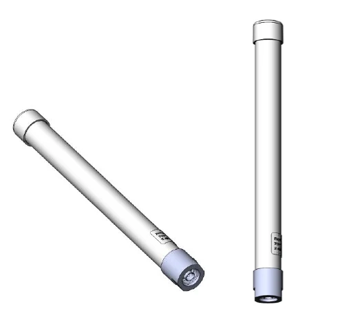
| Heavy-Duty Fiberglass Radome | Unlike standard ABS, the high-tech fiberglass enclosure offers superior structural strength and maximum RF transparency. It effectively protects the internal elements from salt spray, acid rain, and ice formation while maintaining an aesthetically pleasing, low-drag profile. |
|---|
| Unloaded Performance Integrity | By utilizing a full-sized, non-loaded element design, the antenna achieves a stable 9 dBi gain and high radiation efficiency across the entire 1200 MHz bandwidth. |
|---|
| All-Welded Construction | Radiating elements are fully welded to the support booms to eliminate RF inter-modulation (PIM) and ensure the antenna remains stable under high vibration or heavy wind loads up to 200 Km/Hr. |
|---|
| Coastal Protection | The entire assembly is powder-coated to provide an extra layer of protection against saline weather. All fasteners, including screws, nuts, and bolts, are made from high-grade stainless steel to prevent seizing or corrosion. |
|---|
| Rear-Mount Logistics | The mounting hardware is located at the back end of the antenna, allowing for rapid installation on masts up to 51mm (2 inches). This design ensures the mast does not interfere with the antenna's directional beam or front-to-back ratio. |
|---|
| D.C. Grounded Shielding | Operates at D.C. ground, providing a low-resistance path for lightning protection and suppressing atmospheric static to ensure a "quiet" noise floor for sensitive monitoring. |
|---|
| Ultra-Wideband 800–2000 MHz | Covers GSM, LTE, GPS, and L-Band SATCOM in one unit. |
|---|
| Rugged Fiberglass Radome | Elite protection against environmental degradation and mechanical shock. |
|---|
| High-Efficiency 9 dBi Gain | Superior directional focus across the entire band. |
|---|
| All-Welded 6063T6 Aluminum | Maximum durability and PIM-free performance. |
|---|
| MIL-STD-810G Certified | Tested for extreme temperature, shock, vibration, and salt fog. |
|---|
| Rear-End Mounting Plate | Fast installation and optimized radiation patterns. |
|---|
| Marine Grade Stainless Hardware | Total corrosion resistance for naval and coastal use. |
|---|
| Direct Ground Protection | Integrated lightning protection and enhanced noise immunity. |
|---|
| Published detail | In city environments, signals at 800-2000 MHz reflect off glass and concrete surfaces. |
|---|
| The Advantage | The focused 60-degree beamwidth of the LP-800-2000 allows an operator to isolate specific signal paths and ignore unwanted reflections, maintaining a clean link in crowded RF sectors. |
|---|
| Published detail | At frequencies approaching 2 GHz, cable loss is a critical factor. |
|---|
| Recommendation | Use low-loss cables like LMR-400 for runs over 10 meters. Ensure the N-Female termination is weather-sealed with butyl tape; even minor moisture ingress can cause a massive VSWR spike at these frequencies. |
|---|
| Published detail | At 800–2000 MHz, signal wavelengths are short (between 37cm and 15cm). These waves do not "wrap" around buildings effectively; instead, they reflect off glass, metal, and concrete like light off a mirror. |
|---|
| The Reflection Problem | In a dense city center, a target's signal may bounce several times before reaching your mast. Each bounce can cause a "phase shift" or a drop in signal strength. |
|---|
| The LPDA Solution | The 60-degree horizontal beamwidth of the LP-800-2000 acts as an RF "spotlight." By rotating the antenna, an operator can "scan" for the strongest reflected path (Multipath Exploitation) rather than just pointing at the target's last known GPS coordinates. This ensures a stable intercept even when the direct path is blocked. |
|---|
| Visual Ambiguity | Without a radome, an adversary with simple optics can see the orientation of the internal elements. They would immediately know which frequency sub-band you are monitoring (800 MHz vs. 2000 MHz) based on which elements are active. |
|---|
| Directional Obscuration | The tapered radome hides the exact tilt and "boresight" of the antenna, making it impossible for an opponent to determine exactly which window, vehicle, or tower you are currently targeting. |
|---|
| Power Density Focus | The 9 dBi gain acts as a "magnifying glass" for your RF energy. Instead of scattering 250W in all directions, the LP-800-2000 focuses that energy into a tight 60-degree cone. |
|---|
| ERP Calculation | This focus exponentially increases your Effective Radiated Power (ERP). By concentrating the energy, you can successfully "drown out" a legitimate signal from several kilometers away with relatively low input power. |
|---|
| Published detail | At frequencies near 2 GHz, sensitive SIGINT receivers are highly vulnerable to "Noise Floor" elevation, which can mask weak tactical signals. |
|---|
| Static Suppression | High-speed wind or dry air moving across a radome creates "Precipitation Static" (P-Static). On an ungrounded antenna, this creates an electronic "hiss" that raises the noise floor. |
|---|
| The Solution | The LP-800-2000 is D.C. Grounded. It constantly bleeds off this static charge to the mast and earth, ensuring the lowest possible noise floor for detecting low-power or "hidden" L-Band transmissions. |
|---|
| Microwave Cable Selection | At 2000 MHz (2 GHz), cable loss is extreme. Avoid standard RG-58. Use LMR-400 or higher. Every 3 dB of cable loss effectively cuts your jamming power or reception sensitivity in half. |
|---|
| Boresight Alignment | Because the beamwidth is 60 degrees, a 30-degree error in alignment will drop your gain by 3 dB. Use a compass and a map to ensure the antenna is pointed exactly at the target sector for maximum intercept probability. |
|---|
| Connector Weather-Proofing | Microwave connectors are highly sensitive to "impedance bumps." A single drop of moisture in the N-type connector will cause a massive VSWR spike at 2 GHz. Use butyl rubber tape to create a primary moisture seal on all outdoor connections. |
|---|
| Fiberglass Maintenance | While fiberglass is incredibly rugged, ensure the radome is kept free of metallic paints or heavy carbon-based soot, as these materials can attenuate the high-frequency signals before they reach the internal elements. |
|---|
| Frequency stated in title | 800-2000 MHz |
|---|
| Gain stated in title | 9 dBi |
|---|
| Category | Radomes, Enclosures & Replacement Parts |
|---|