| Model | LP-800-6000 |
|---|
| Frequency (manufacturer model field) | 800-6000MHz |
|---|
| Bandwidth (manufacturer model field) | 800-6000MHz |
|---|
| Gain (manufacturer model field) | 8 dBi |
|---|
| Frequency Range | 800-6000MHz |
|---|
| Gain | 8 dBi |
|---|
| Bandwidth | 800-6000 MHz |
|---|
| Polarization | Horizontal or Vertical |
|---|
| Radiation Pattern | Directional |
|---|
| Beamwidth -3dB. | 60+/-5 Degrees Typical |
|---|
| Front to Back Ratio | 17+/-2 dB. Typical |
|---|
| VSWR - Equal To or Better Then | Less Than 2.5:1 |
|---|
| RF Power Handling Capacity | 100 Watts @ 6GHz |
|---|
| Input Termination | N-Female |
|---|
| Lightning Protection | Direct Ground |
|---|
| Antenna Materials | Aluminum, Fiberglass, SS |
|---|
| Mounting Hardware -Materials | Marine Grade Stainless Steel |
|---|
| Wind Rating | 200 Km/Hr. |
|---|
| Overall Length | 450 mm |
|---|
| Shipping Length | 550 mm |
|---|
| Support Boom -Material - O.D. | 6063T6 AluminumSquare Tube |
|---|
| Elements - Materials- Cross Section - Outer Diameter | 6063T6 AluminumRound Rod |
|---|
| Maximum Mount Pipe Diameter | 51mm (2 Inches) |
|---|
| Radome Material | High Strength Fiberglass |
|---|
| Gross Weight | 2.5 Kgs. Approx |
|---|
| Operating Temperature | (-)30 to +70 Degrees Celsius |
|---|
| Storage Temperature | (-)40 to +80 Degrees Celsius |
|---|
| Humidity | 0 to 95% RH |
|---|
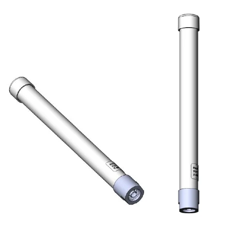
| High-Tech ABS Radome | The antenna is completely enclosed in a ruggedized, RF-transparent ABS radome. This tapered design significantly reduces wind loading, prevents ice formation, and obscures the internal elements for tactical ambiguity. |
|---|
| Unloaded Efficiency | Unlike compact antennas that use lossy loading techniques, the LP-800-6000 utilizes full-sized radiating elements. This ensures a stable 9 dBi gain and high radiation efficiency from 800 MHz up to 6.0 GHz. |
|---|
| Fast Installation Mounting | The mounting hardware is permanently welded at the rear of the support boom. This allows for rapid attachment to a standard 51mm (2-inch) mast while eliminating the risk of the mast interfering with the antenna’s directional beam. |
|---|
| MIL-STD-810G Certified | The antenna has undergone rigorous military-standard testing for high/low temperatures, shock, vibration, humidity, and salt fog. It is specifically treated for coastal deployments where saline air is a concern. |
|---|
| Fully Welded Architecture | All radiating elements are fully welded to the support booms. This prevents mechanical fatigue and eliminates RF inter-modulation (PIM), ensuring a clean signal even at high power levels. |
|---|
| Integrated Lightning Protection | The antenna operates at D.C. ground, providing a low-resistance path to protect sensitive receivers from lightning strikes and suppressing atmospheric static for a "quiet" noise floor. |
|---|
| Ultra-Wideband 800–6000 MHz | Covers GSM, LTE, 5G, Wi-Fi, and C-Band in a single unit. |
|---|
| Rugged Tapered Radome | Protects against ice, wind (200 KMPH), and visual detection. |
|---|
| High-Efficiency 9 dBi Gain | Superior directional precision across the entire band. |
|---|
| All-Welded 6063T6 Aluminum | Maximum durability and PIM-free performance. |
|---|
| MIL-STD-810G Compliance | Engineered for the world's harshest environments. |
|---|
| Rear-End Master Mounting | Eliminates mast-induced pattern distortion. |
|---|
| Marine Grade Stainless Hardware | Total corrosion resistance for naval and coastal use. |
|---|
| D.C. Grounded Shielding | Integrated lightning protection and noise immunity. |
|---|
| Published detail | The 800-6000 MHz range covers almost all modern commercial data standards. |
|---|
| The Advantage | The focused 60-degree beamwidth allows an operator to isolate a specific cellular tower or Wi-Fi access point in a crowded urban environment, reducing "background noise" from neighboring transmitters. |
|---|
| Published detail | At frequencies up to 6000 MHz (6 GHz), signal attenuation in the cable is the primary cause of system failure. |
|---|
| Recommendation | Use high-performance, low-loss cables like LMR-600 or corrugated copper feeders for long runs. Ensure the N-Female termination is weather-sealed with butyl tape; at 6 GHz, even minor moisture can cause a massive VSWR spike. |
|---|
| Published detail | At 0.8–6.0 GHz, signal wavelengths are very short (between 37cm and 5cm). These signals do not "wrap" around buildings; they reflect off them or are blocked entirely. |
|---|
| The Reflection Problem | In a city, a 5 GHz Wi-Fi or 5G signal may bounce five times before reaching your antenna. Each bounce can flip the polarization from vertical to horizontal. |
|---|
| The LPDA Solution | While the LP-800-6000 is a single-polarized antenna, its 60-degree horizontal beamwidth allows an operator to "scan" reflections off neighboring buildings to find the strongest signal path (Multipath Exploitation) rather than just pointing at the target's GPS coordinates. |
|---|
| Visual Ambiguity | Without a radome, an adversary with binoculars can see the size of the internal elements and immediately know if you are monitoring low-band (800 MHz) or high-band (6 GHz) frequencies. |
|---|
| Directional Obscuration | The radome hides the exact tilt and orientation of the internal array, making it impossible for an opponent to determine exactly which window or tower you are targeting. |
|---|
| Published detail | To disrupt a high-speed data link (like a 5.8 GHz drone command link or a 5G relay), you must achieve a superior Jamming-to-Signal (J/S) ratio. |
|---|
| Power Density | The 9 dBi gain acts as a "magnifying glass" for your RF energy. Instead of scattering 100W in all directions, the LP-800-6000 focuses that energy into a tight 60-degree cone. |
|---|
| Efficiency | This focused beam exponentially increases the effective radiated power (ERP) on the target receiver, successfully drowning out the legitimate signal even at extended ranges. |
|---|
| Published detail | At 6 GHz, sensitive SIGINT receivers are highly vulnerable to "Noise Floor" elevation. |
|---|
| Static Suppression | High-speed wind or dry air moving across an antenna creates "Precipitation Static" (P-Static). On an ungrounded antenna, this sounds like a constant hiss that masks weak signals. |
|---|
| The Solution | The LP-800-6000 is D.C. Grounded. It constantly bleeds off this static charge to the mast, ensuring the lowest possible noise floor for detecting low-probability-of-intercept (LPI) signals. |
|---|
| Microwave Cable Integrity | At 6000 MHz, cable loss is extreme. Standard RG-58 is useless. Use LMR-600 or high-grade corrugated copper. Every 3 dB of cable loss cuts your effective jamming power in half. |
|---|
| Connector Weather-Proofing | Microwave frequencies are highly sensitive to "impedance bumps." A single drop of moisture in the N-type connector will cause a massive VSWR spike at 6 GHz. Use professional-grade butyl rubber tape for all outdoor seals. |
|---|
| Mast Stability | Because the beamwidth is relatively narrow (50–60 degrees), a "swaying" mast will cause the signal to fluctuate (scintillation). Ensure the 51mm mast is rigidly mounted and guyed if necessary. |
|---|
| Line-of-Sight (LOS) Verification | At these frequencies, even a single tree or a thin plywood wall can attenuate the signal by 10–20 dB. Always ensure a clear optical line-of-sight between the LP-800-6000 and your target for maximum performance. |
|---|
| Frequency stated in title | 800-6000 MHz |
|---|
| Gain stated in title | 9 dBi |
|---|
| Category | Radomes, Enclosures & Replacement Parts |
|---|