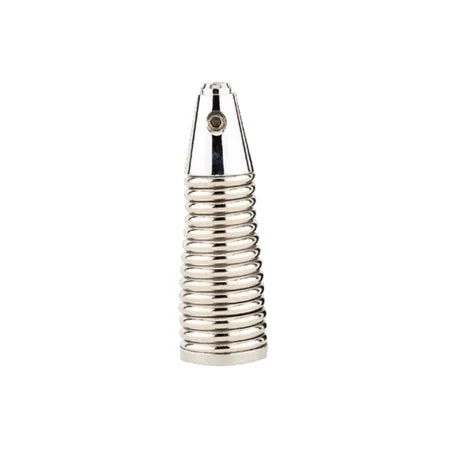
| Model | LPDP-500-2000 |
|---|
| Frequency (manufacturer model field) | 500-2000MHz |
|---|
| Bandwidth (manufacturer model field) | 500-2000MHz |
|---|
| Gain (manufacturer model field) | 9 dBi |
|---|
| Frequency Range | 500-2000 MHz |
|---|
| Gain | 9 dBi |
|---|
| Bandwidth | Entire Band |
|---|
| Polarization | Vertical & Horizontal |
|---|
| Input Impedance | 50 Ohms |
|---|
| Horizontal Beamwidth -Half Power Points | 70 +/-10 Degrees Typical |
|---|
| Front to Back Ratio | 16 +/-2 dB. Typical |
|---|
| VSWR - Equal To or Better Then | Better Than 2.5:1 |
|---|
| RF Power Handling Capacity | 250 Watts |
|---|
| Input Termination | 2 x N-Female |
|---|
| Lightning Protection | Direct Ground |
|---|
| Antenna Materials | 6063T6 Aluminum Alloy |
|---|
| Mounting Hardware -Materials | Marine Grade Stainless Steel |
|---|
| Wind Rating | 200 Km/Hr. |
|---|
| Overall Length | 600 mm |
|---|
| Shipping Length | 700 mm |
|---|
| Support Boom -Material - O.D. | AluminumSquare Tube |
|---|
| Elements - Materials- Cross Section - Outer Diameter | AluminumRound Rod |
|---|
| Mounting Clamps Position | At rear end of support boom |
|---|
| Maximum Mount Pipe Diameter | 51 mm (2 Inches) |
|---|
| Gross Weight | 4.5 Kgs. |
|---|
| Operating Temperature | (-) 30 to + 70 Degrees Celsius |
|---|
| Storage Temperature | (-) 40 to + 80 Degrees Celsius |
|---|
| Humidity | 0 to 95% RH |
|---|
| Simultaneous Dual Processing | Equipped with 2 x N-Female ports, the antenna allows for concurrent handling of vertical and horizontal polarizations. This provides true polarization diversity, ensuring no signal is lost due to ionospheric rotation or multipath fading. |
|---|
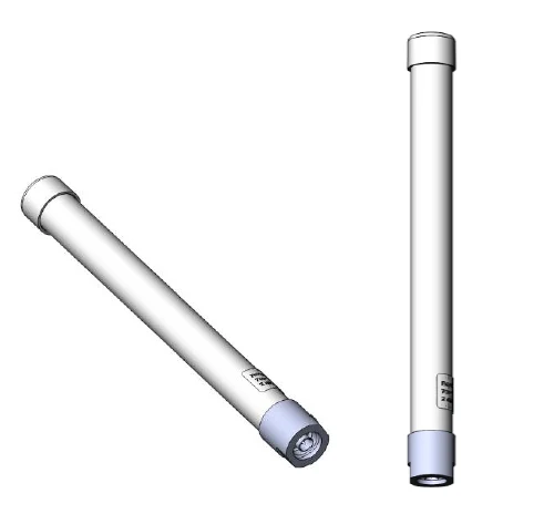
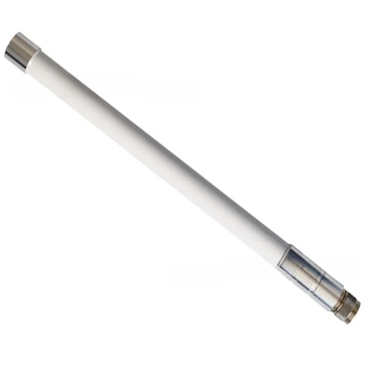
| Advanced ABS Radome | The cylindrical, tapered enclosure is crafted from RF-transparent ABS. It is specifically designed to minimize wind loading and prevent ice formation, maintaining the antenna's 9 dBi gain in the harshest global climates. |
|---|
| RF Stability | All internal elements are fully welded to the support booms. This prevents RF inter-modulation and ensures the antenna remains electrically stable over its entire service life. |
|---|
| Environmental Shielding | The antenna is finished in a Military Olive Green powder coating. The internal components are protected by an epoxy-based finish to resist salt spray, corrosive gases, and acid rain. |
|---|
| D.C. Grounded Architecture | The entire system operates at D.C. ground, providing an integrated low-resistance path for lightning protection and suppressing atmospheric static for a "quiet" noise floor. |
|---|
| Marine-Grade Hardware | All fasteners, screws, and bolts are made of Type 316 marine-grade stainless steel, ensuring the mounting fixtures remain operable in coastal environments. |
|---|
| Dual-Polarized Cross-Element Architecture | Instantaneous capture of all signal polarizations. |
|---|
| Ruggedized ABS Radome | Obscures internal element orientation for tactical stealth and weather protection. |
|---|
| Published detail | 500–2000 MHz Bandwidth: Covers UHF, GSM, and LTE bands in a single directional unit. |
|---|
| High-Efficiency 9 dBi Gain | Focused 65-degree beamwidth for precise signal targeting. |
|---|
| MIL-STD-810G Certified | Tested for extreme naval and desert environmental cycles. |
|---|
| Rear-Mount Installation | Permanently welded mounting fixture for rapid setup on masts up to 52mm. |
|---|
| Type 316 Stainless Hardware | Total corrosion resistance for shipboard and coastal use. |
|---|
| Low Wind Loading | Tapered radome design ensures stability in 200 Km/Hr winds. |
|---|
| D.C. Grounded Shielding | Integrated lightning protection and high noise immunity. |
|---|
| The "Null" Problem | A single-polarized antenna will experience deep signal fades (up to 30 dB) when the incoming wave's polarization rotates away from the antenna's orientation. |
|---|
| The Diversity Solution | By monitoring the Vertical and Horizontal ports simultaneously, your SIGINT system can perform Maximum Ratio Combining (MRC). When the signal fades on the vertical plane, it almost always "peaks" on the horizontal plane, ensuring a continuous, high-quality intercept of data bursts. |
|---|
| Visual Obscuration | The ABS Radome hides the internal element structure. An adversary cannot visually determine if the antenna is currently focused on 500 MHz (large elements) or 2000 MHz (small elements), nor can they see the exact polarization tilt. |
|---|
| Environmental Integrity | In high-speed tactical movements, open elements can "whistle" or vibrate, creating a mechanical signature. The tapered radome is acoustically quiet and aerodynamically stable, rated for 200 Km/Hr winds. |
|---|
| Published detail | Monitoring the 500-2000 MHz band requires high sensitivity to pick out weak tactical signals among the noise. |
|---|
| Low-Noise Floor | The D.C. Grounded design and the protective radome prevent "Precipitation Static" (P-Static). During rain or wind, unshielded antennas build up static charge that raises the noise floor; the LPDP-500-2000 stays "quiet," allowing you to see signals just above the thermal limit. |
|---|
| Isolation for Jamming | The 20 dB Cross-Polarization Discrimination allows you to jam a target on one polarization (e.g., Vertical) while simultaneously monitoring the environment on the other (Horizontal) with minimal interference. |
|---|
| Published detail | The 65-degree horizontal beamwidth acts as a precision "floodlight" for the 500–2000 MHz band. |
|---|
| Target Concentration | Instead of wasting 200W of jamming power in 360 degrees, the LPDP-500-2000 concentrates that energy into a narrow sector. This significantly increases the Jamming-to-Signal (J/S) ratio at the target's receiver. |
|---|
| Front-to-Back Protection | The 18 dB F/B ratio is critical for protecting your own team. It ensures that while you are jamming or monitoring a target, your own communication equipment located behind the antenna remains functional and unjammed. |
|---|
| Coaxial Selection | At 2000 MHz (2 GHz), cable loss is significant. Use LMR-600 or higher for runs exceeding 10 meters. A 10-meter run of standard RG-58 would lose a massive portion of your power. |
|---|
| Radome Maintenance | While ABS is rugged, ensure the radome is kept free of metallic paint or heavy carbon-based dirt, which can attenuate high-frequency signals. |
|---|
| Mounting Alignment | Ensure the antenna is mounted level. Because the beamwidth is only 55–65 degrees, a tilt of just 10 degrees can move the "Peak Gain" off the target, reducing your effective range. |
|---|
| Connector Sealing | Use professional-grade weatherproofing. In the 2 GHz range, a single drop of water in the N-Female connector will cause a massive VSWR spike and potentially damage your 200W transmitter. |
|---|
| Frequency stated in title | 500-2000 MHz |
|---|
| Category | Radomes, Enclosures & Replacement Parts |
|---|