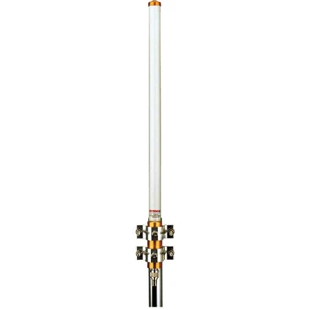
| Model | JCS10-2100 |
|---|
| Frequency (manufacturer model field) | 2000-2170MHz |
|---|
| Bandwidth (manufacturer model field) | 2100-2170MHz |
|---|
| Gain (manufacturer model field) | 10 dBi |
|---|
| Frequency Range | 2000-2170 MHz |
|---|
| Gain | 10 dBi |
|---|
| Bandwidth | 2 - 2.17 GHz |
|---|
| Polarization | Vertical |
|---|
| Input Impedance | 50 Ohms |
|---|
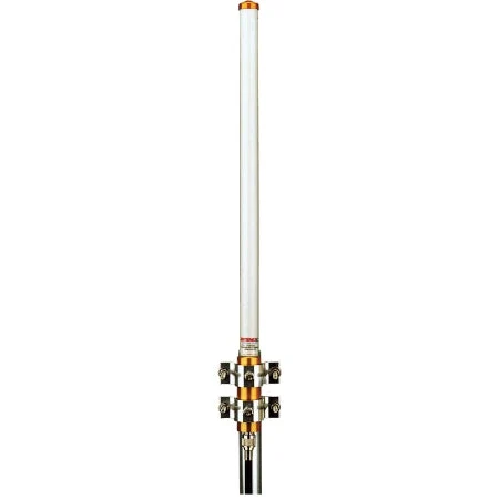
| Radiation Pattern | Omni-directional |
|---|
| VSWR - Equal To or Better Then | 2:1 |
|---|
| RF Power Handling Capacity | 200 watts CW |
|---|
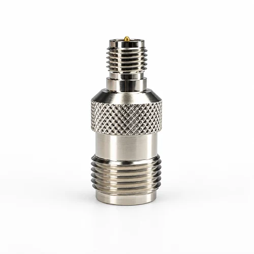
| Input Termination | N-Female |
|---|
| Antenna Materials | Aluminum, SS, Brass & ABS |
|---|
| Mounting Hardware -Materials | Stainless Steel |
|---|
| Wind Rating | 100 KMPH |
|---|
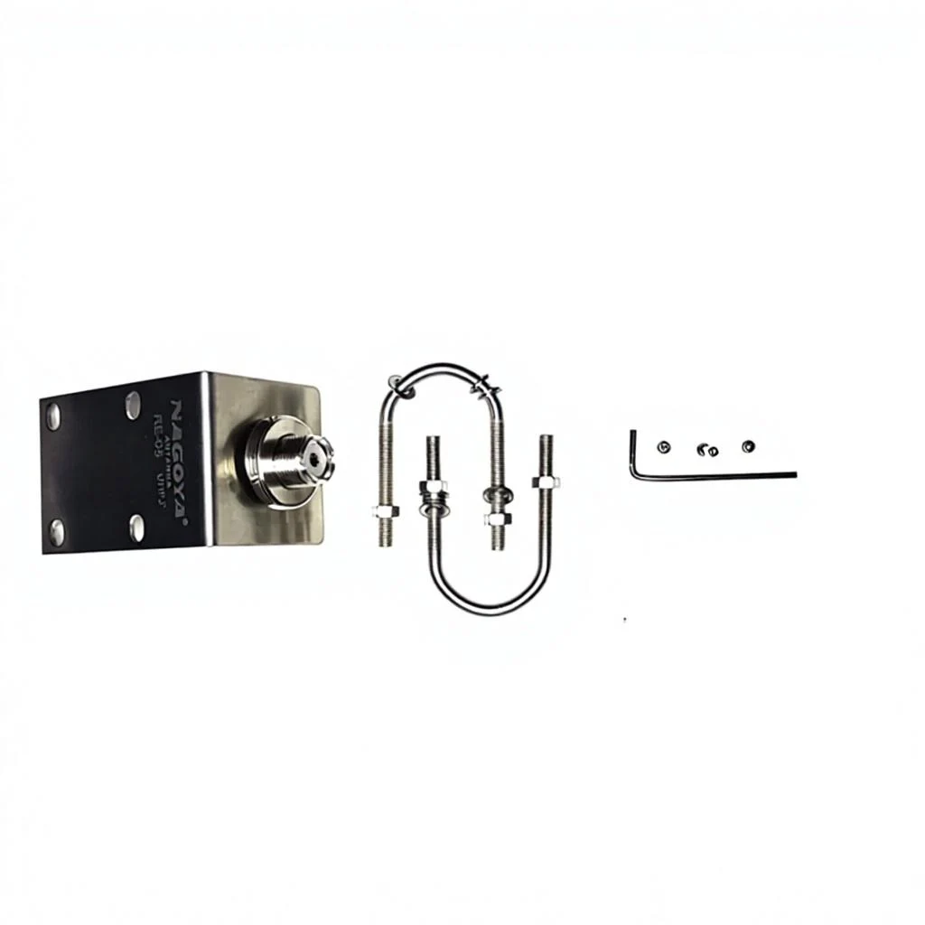
| Mounting Type | NATO Flange or Customized |
|---|
| Overall Length | 1500 mm |
|---|
| Shipping Length | 1600 mm |
|---|
| Support Pipe O.D. | 51 mm |
|---|
| Support Pipe Material | 6063T6 Aluminum Alloy |
|---|
| Radome Material | ABS |
|---|
| Radome Outer Diameter | 45 mm |
|---|
| Radiating Elements - Material | High Quality Brass |
|---|
| Gross Weight | 2 Kgs. |
|---|
| Operating Temperature | MIL-STD-810F, Method 504.1 |
|---|
| Storage Temperature | MIL-STD-810F, Method 502.4 |
|---|
| Humidity | MIL-STD-810F, Method 507.4 |
|---|
| High-Efficiency Collinear Array | By stacking high-quality brass radiating elements in phase, the antenna achieves a narrow 9-degree vertical beamwidth. This focuses RF energy toward the horizon, maximizing terrestrial range and ensuring signal saturation of ground-based triggers. |
|---|
| Extreme 400W Power Handling | Engineered to handle 400 Watts CW (Continuous Wave), this antenna provides the necessary throughput for high-intensity, persistent wide-area signal denial. |
|---|
| Ground Independent Operation | Designed to maintain a smooth VSWR of better than 1.5:1 across the entire bandwidth without the requirement of multiple antennas or field tuning. |
|---|
| Shock-Absorbing Spring Base | Features a heavy-duty tampered steel spring at the base. This allows the 1.5-meter array to flex during off-road maneuvers or impact with low-hanging obstacles, protecting the antenna and vehicle mount from structural failure. |
|---|
| Ruggedized Materials | Constructed using 6063T6 ultra-corrosion resistant aluminum alloy and enclosed in a high-strength ABS radome (45 mm diameter). All components are finished in Military Olive Green powder coating for maximum UV and chemical protection. |
|---|
| MTBF & Workmanship | Boasts a Mean Time Between Failure (MTBF) of 25,000 hours and is manufactured to IPC-610 standards, ensuring elite reliability in front-line combat zones. |
|---|
| Extreme Power Density | With a 400-Watt CW power handling capacity and 10 dBi gain, this antenna provides one of the most potent electronic "denial zones" in its class, ensuring high-intensity signal saturation across the 2.1 GHz band. |
|---|
| Focused Standoff Range | The ultra-narrow 9-degree vertical beamwidth compresses RF energy toward the horizon. This prevents power wastage in the sky and maximizes the effective terrestrial range against ground-based triggers and low-altitude threats. |
|---|
| Dynamic Shock Absorption | The integrated tampered steel spring base is a critical tactical advantage, allowing the 1.5-meter antenna to absorb mechanical shocks, vibrations, and physical impacts during high-speed, off-road maneuvers. |
|---|
| Superior Impedance Matching | Maintains an exceptional VSWR of better than 1.5:1 across the entire bandwidth. This ensures maximum power transfer from the transmitter to the antenna, protecting sensitive RF hardware from reflected power damage. |
|---|
| MIL-STD-810F Battle-Hardened | Rigorously tested for 25,000 hours MTBF and compliant with extensive military protocols, including bouncing transit, solar radiation, and salt fog, ensuring 24/7 reliability in frontline combat. |
|---|
| Rapid NATO Integration | The standard NATO 4-hole mounting pattern allows for immediate, "bolt-on" deployment across a wide fleet of armored personnel carriers (APCs), tanks, and tactical command vehicles. |
|---|
| Zero-Maintenance Design | The factory-tuned collinear architecture and rugged ABS radome require no periodic calibration or field adjustments, reducing the logistical burden on maintenance crews. |
|---|
| Published detail | 3G/UMTS RCIED Defeat: Primary defense against Remote Controlled Improvised Explosive Devices that utilize the 2100 MHz cellular band for remote triggering. |
|---|
| Extended Convoy Shielding | Mounted on lead and rear vehicles to provide a high-power electronic shield for mobile tactical units, VIP motorcades, and logistics columns. |
|---|
| High-Band Communication Denial | Targeted disruption of adversary high-speed microwave data networks, tactical mesh radios, and wireless command-and-control (C2) nodes. |
|---|
| Counter-UAS (C-UAS) | Directional and omnidirectional disruption of drone command, control, and high-frequency video telemetry links. |
|---|
| Signals Intelligence (SIGINT) | Used as a high-gain discovery antenna for intercepting weak signals or performing high-speed spectrum surveillance in the S-band. |
|---|
| Tactical Operations Center (TOC) Security | Permanent or temporary installation to deny unauthorized wireless access and provide local electronic protection for command hubs. |
|---|
| Electronic Warfare (EW) | Primary defense against RCIED (Remote Controlled IED) triggers and high-power signal denial in the 2.1 GHz UMTS band. |
|---|
| Signals Intelligence (SIGINT) | The high-gain profile and clean noise floor allow for the interception of weak signals and high-speed spectrum scanning. |
|---|
| Global Monitoring | The 360-degree horizontal coverage acts as a persistent electronic "tripwire" for theater situational awareness. |
|---|
| Frequency stated in title | 2100-2170 MHz |
|---|
| Gain stated in title | 10 dBi |
|---|
| Category | VHF, UHF & General-Purpose Antennas |
|---|